Class 6
Today we focused on electronic production. We learned how to make a brand new PCB board, including how it worked with all its components, how to solder it and uploarfd the bootloader on it. With a welding gun and welding stick, I welded the small parts together, such as the capacitor, LED light and resistor. After that, I connected the PCB board to my laptop computer using a cable, and I uploaded some codes as an example from the software Arduino. Therefore, the lights on the board could turn on and turn off in a frequency based on my preference.
Image 0601
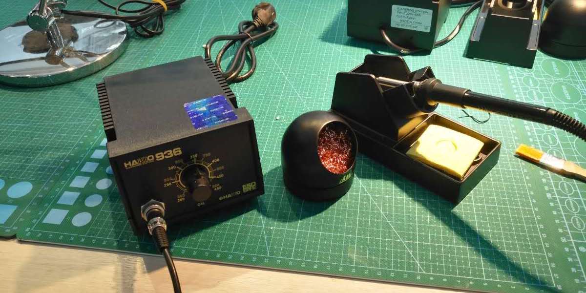
This image shows the soldering station we used to manufacture the PCB board called Shanghaino. It was consisted of three main parts, a cleaner, a support and a heater which was connected to the welding gun.
These two images show the scene of our working. We were trying to weld together the components of a PCB board with the help of instructor Saverio and assistant Travis.
Image 0602
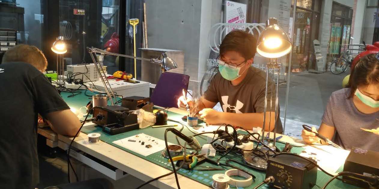
Image 0603
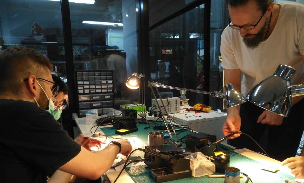
Image 0604
The things listed on the whiteboard were the components we needed for welding the PCB board called Shanghaino.
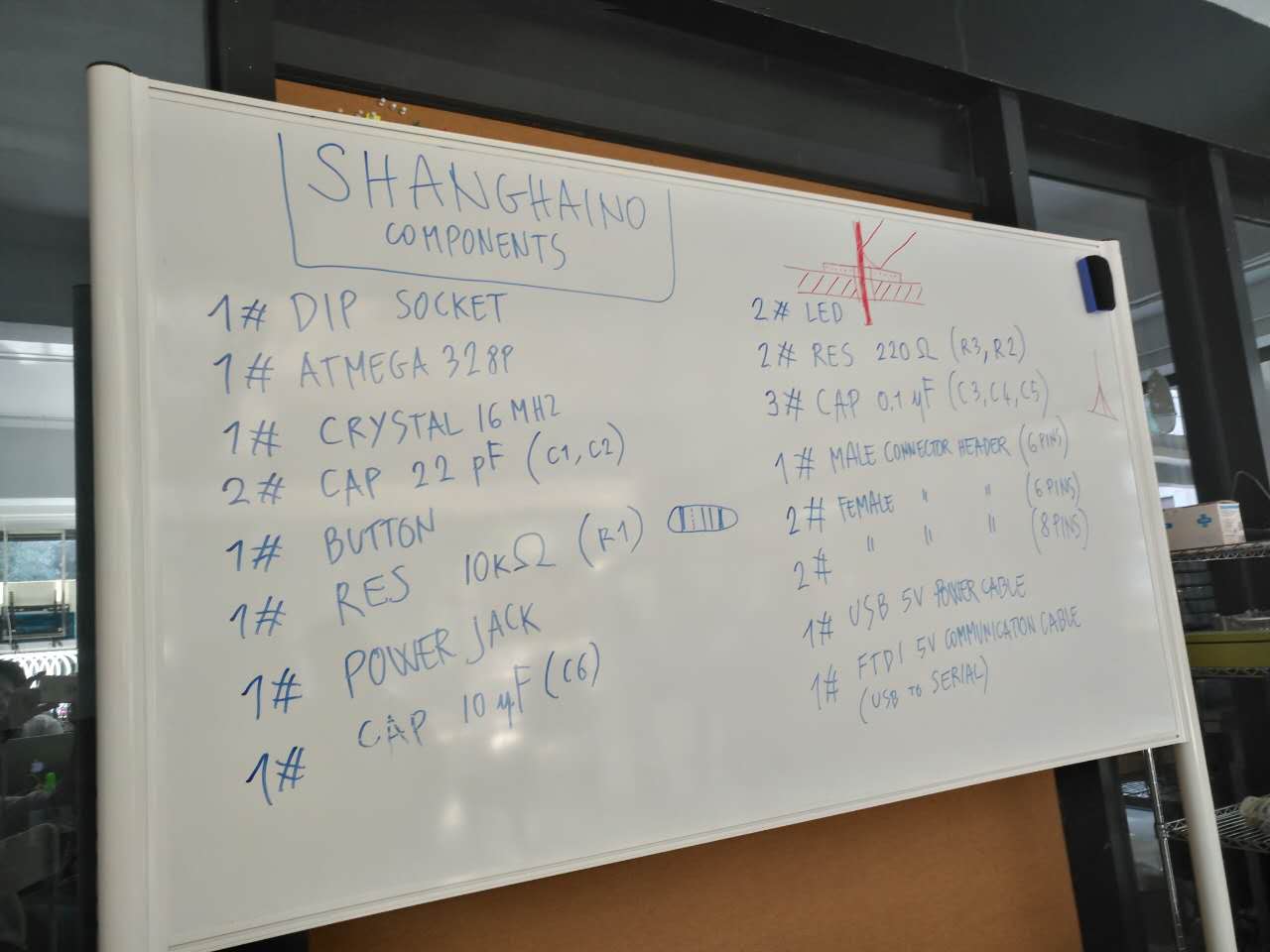
Image 0605
This is what the back of the PCB board looked like. It was not easy to weld it, as the solder must be spherical and smooth so that it could stably conduct electricity.
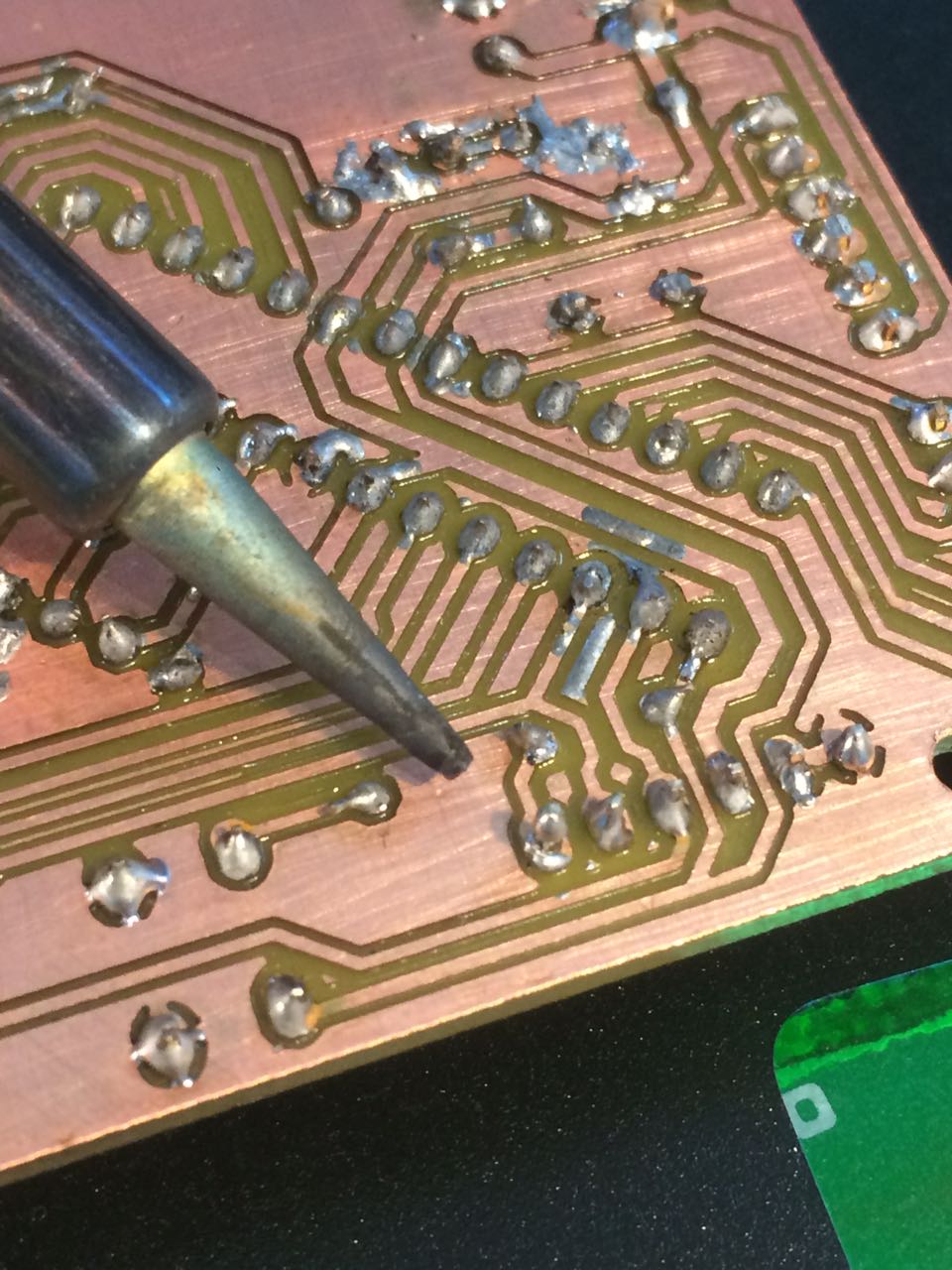
Image 0607
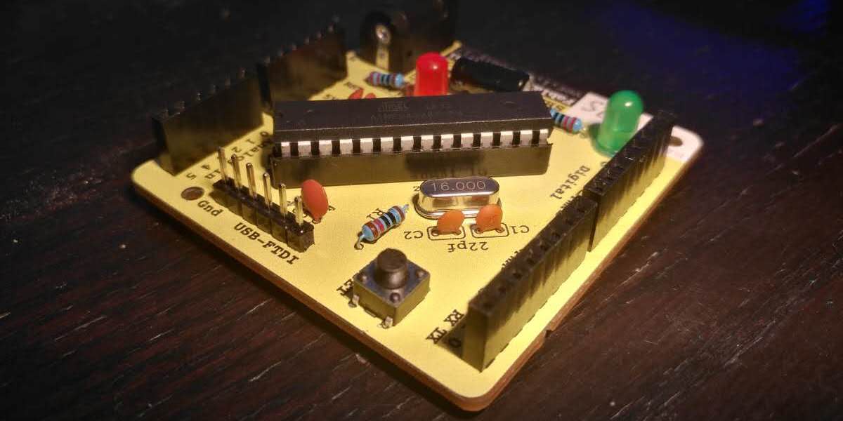
This is what PCB board looked like when it was finished. The shimmer of the green light could be controlled using Arduino that was installed on my laptop computer.
