Class 6: Basic for designing a PCB
In this class, we will do something concerned with the electronic--PCB(Printed Circuit Board). However, firstly taking it easy. After figuring out what each component can do, we will initially learn how to "print" the circuit board.
Tools
Step1:How printer works?
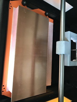
There are many types of PCB printers on market and we use the one without laser. It just work with powerful engineer ,and precise and different screw head to make a exact print on the board.
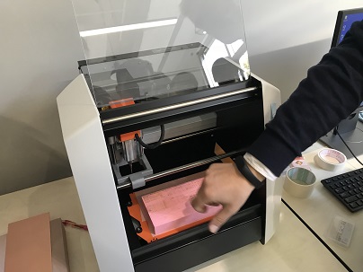
From the picture above, we have a blur view of the printer.
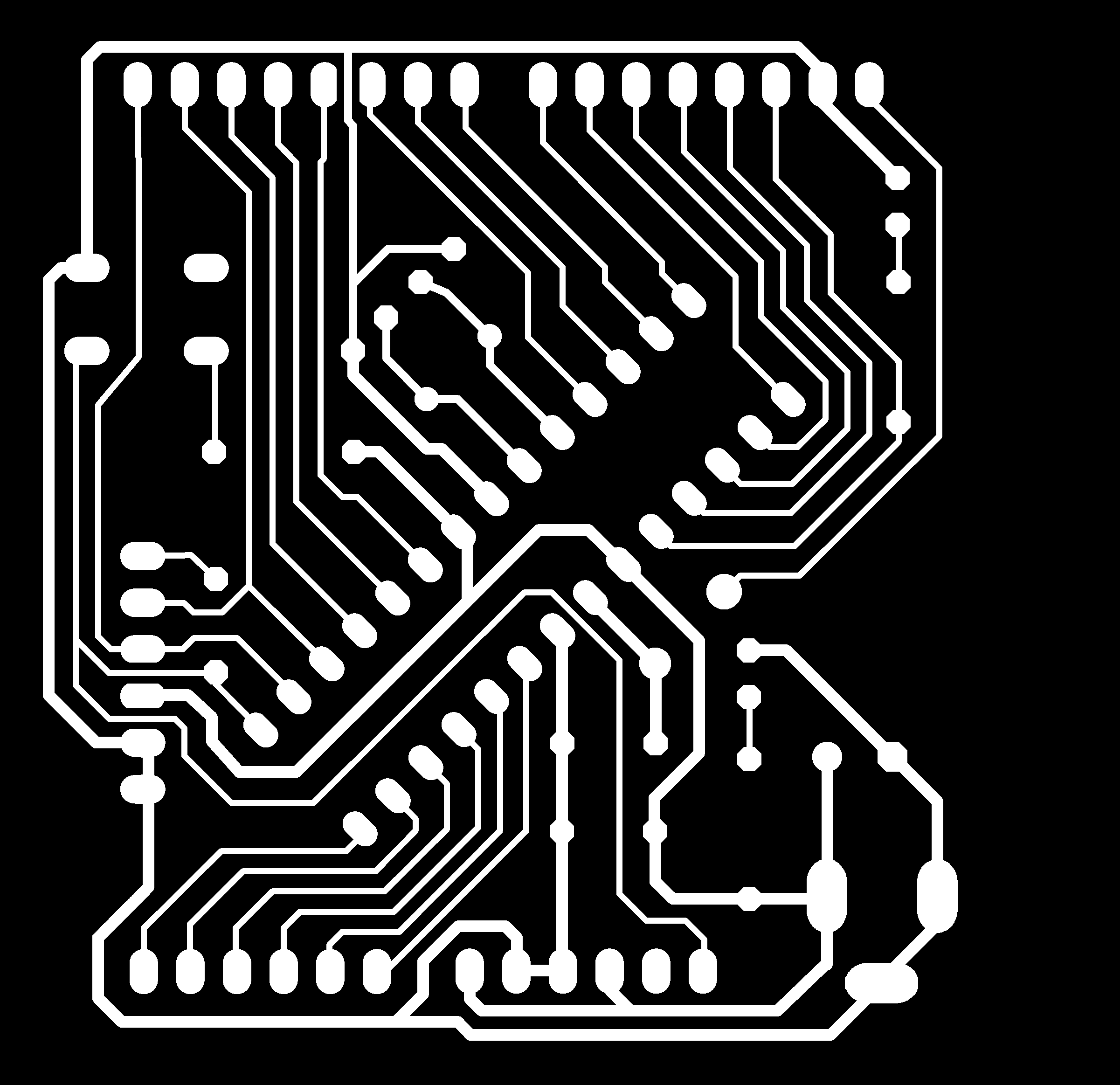
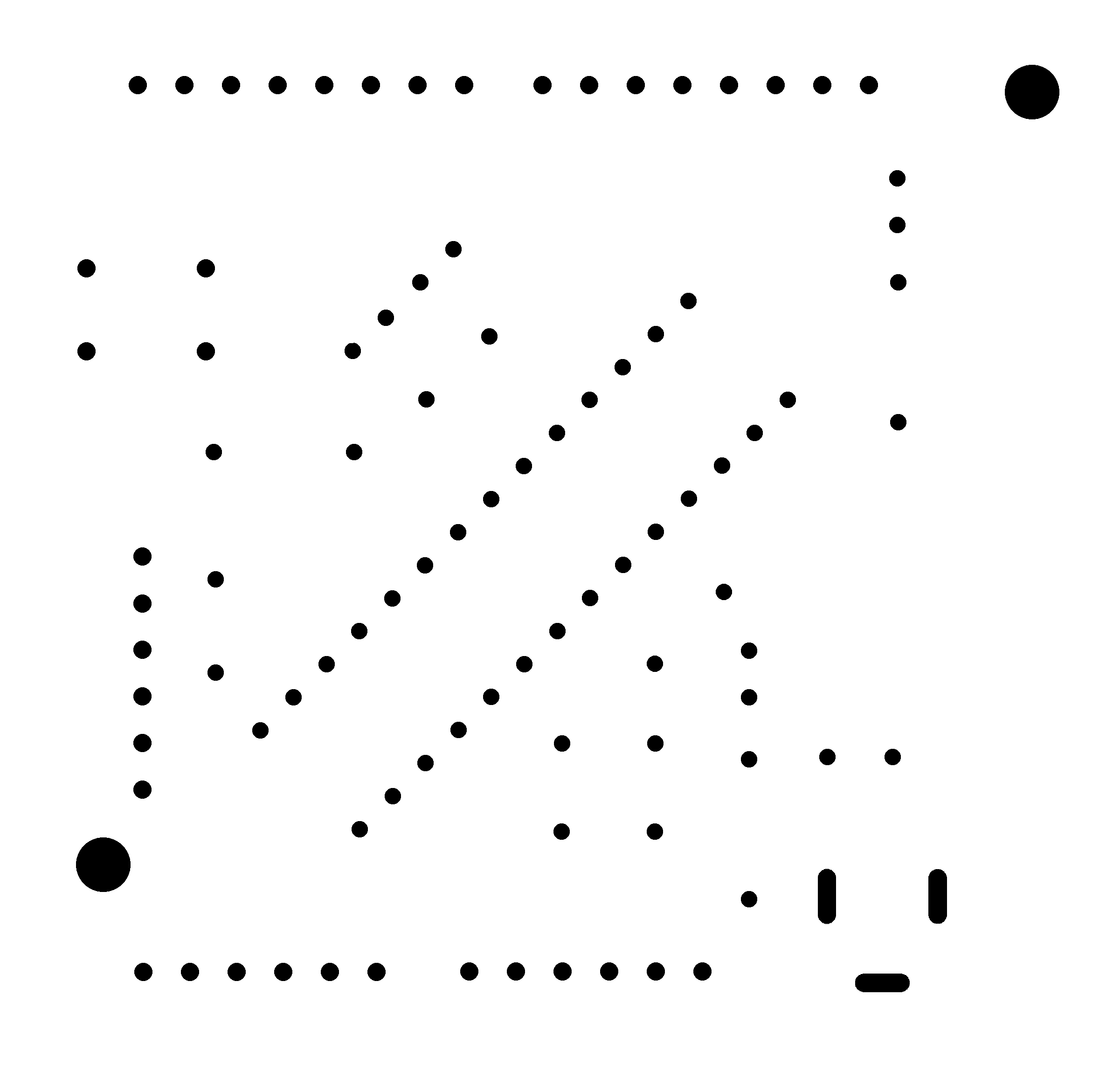
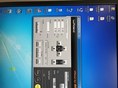
Step2:Adjust the PCB on the computer

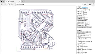
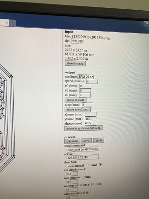
Step3:Adjust the parameter on the software.
Step4:Question
Question
Actually, when I do the operation, I really forget how to make a perfect surface! This could be a big problem I think.